PROYECTO FINAL

Publicado: 10 09, 2013 en Laboratrio 1

LEER REVOLUCIONES DC BRUSHLESS (ventilador PC) CON ARDUINO

DESCRIPCION:

Es un ventilador de PC llamado Brushless Fan donde por medio del programa Arduino uno, podemos ejecutar el codigo que lee las revoluciones en el ventilador.

MATERIALES:

  • Arduino 
  • 2 Resistencias 10K
  • 1 DC Brushless Fan (ventilador de PC)
  • 1- Protoboard
  • 6 cables

PROCESO MONTAJE

1385599829534 1385599712780

1385599618398 1385599609124

1385595068132

CODIGO ARDUINO

int NbTopsFan;
int Calc;

int hallsensor = 2;
typedef struct{

char fantype;

unsigned int fandiv;

}

fanspec;

//Definitions of the fans
fanspec

fanspace[3]={{0,1},{1,2},{2,8}};
char fan = 1;

void rpm ()
{

NbTopsFan++;

}

void setup()

{

pinMode(hallsensor, INPUT);

Serial.begin(9600);

attachInterrupt(0, rpm, RISING);

}
void loop ()
{

NbTopsFan = 0;
sei();
delay (1000);
cli();
Calc = ((NbTopsFan * 60)/fanspace[fan].fandiv);

Serial.print (Calc, DEC);

Serial.print (» rpm\r\n»);

}

VIDEO MONTAJE

Laboratorio 13

Publicado: 10 09, 2013 en Laboratrio 1

DESCRIPCIÓN:

Utilizando Processing, manipular en la pantalla del computador una figura animada, a partir de los datos leídos desde el Arduino y un Joystick shield.

MATERIALES:

-Hardware Arduino UNO
-Hardware JoystickShield (para Arduino)

PROCESO DE MONTAJE

  • Disponer de todos loa materiales para el laboratorio.

parte1

  • seguimos con el montaje  del Joystick shield en el arduino y conectamos el cable a la CPU

parte2parte4

VENTA DEL PROCESSING

parte5

CÓDIGO ARDUINO

char button0=3, button1=4, button2=5, button3=6;

void setup(void)
{

pinMode(button0, INPUT);
digitalWrite(button0, HIGH);

pinMode(button3, INPUT);
digitalWrite(button3, HIGH);

Serial.begin(9600);
}

void loop(void)
{

if(analogRead(1)>800)
{
Serial.print(1);
}
else if(analogRead(1)<200)
{
Serial.print(2);
}

if(analogRead(0)>800)
{
Serial.print(3);
}
else if(analogRead(0)<200)
{
Serial.print(4);
}

if(digitalRead(button0)==0)
{
Serial.print(5);
}

if(digitalRead(button3)==0)
{
Serial.print(6);
}

delay(100);
}

CÓDIGO PROCESSING

import processing.serial.*;
int x=550;
int y=550;//el punto centro de la pantalla
int grados=0;//inicio de grados en el que se encuentra el triangulo
Serial port;//puerto por el que vamos a recibir los datos
int valor = 0;
//int valor2=550;
void setup()
{
//println(Serial.list());
port = new Serial(this, Serial.list()[0], 9600);
//new Serial(this, COM[5], 9600);
size(1000,600);//tamaño de la ventana
frameRate(100);// especifica el numero de fotogramas que muestra por segundo
smooth();//suavizar
fill(25,90,40);//color del triangulo ROJO
}
void draw ()
{
while (port.available() > 0)
{
String cadena =»00″+port.readString(); //Lectura de datos desde arduino
valor = int(cadena.substring(2,cadena.length()));
println(cadena + «:» + valor);
}

background (30,30,30);//color de fondo
pushMatrix();//entrada a la pila de matriz
translate(x, y);//trasladamos el triagulo en pantalla con respecto a su estado
rotate(radians(grados));//rotamos el triangulo el numero de grados indicado
triangle(0, 40, -40, -40, 40, -40);//pintar el triangulo
popMatrix();//restaura la pila de matriz

//Condiciones que dependen del los valores recibidos desde arduino (movimientos de joystick)
if (valor == 1)
{
valor=0;
y-=10;
if (y<10) y=30;
}

if (valor == 2)
{
valor=0;
y+=10;
if (y>400) y=400;
}

if (valor == 3)
{
valor=0;
x+=10;
if (x>400) x=400;
}

if (valor == 4)
{
valor=0;
x-=10;
if (x<10) x=30;
}

if (valor == 5)
{
valor=0;
grados+=5;
if (grados>360) grados=0;

}

if (valor == 6)
{
valor=0;
grados-=5;
if (grados<0) grados=360;
}

}

VÍDEO DEL FUNCIONAMIENTO


Laboratorio 11

Publicado: 10 09, 2013 en Laboratrio 1


DESCRIPCIÓN

Controlar una matrix de LEDs de 8×5 cableada directamente al Arduino, para mostrar un mensaje letra por letra, desplazándose de derecha a izquierda.

MATERIALES

  • 26— resistencias de 330 ohmios
  • 1 — una matrix de leed 8×5
  • 1 — plataforma arduino uno R3
  • 1 — protoboard

PROCESO MONTAJE

  • Disponer de todos loa materiales para el laboratorio a seguir.

IMG_1062[1]

  • seguimos con el montaje  en la protoboard.

IMG_1060[2]

  • Luego instalacion de cables y conexion al pc.

IMG_1061[1]

CODIGO ARDUINO

#include <FrequencyTimer2.h>

//matrix 5x5
//se declara la variable temCol de tipo entero inicializada en 5
int temCol = 5; 
//se declara la variable temFil de tipo entero inicializada en 5
int temFil = 5; 

//se definen las matrices de letras [A-Z]
#define A { \
{1, 1, 1, 1, 1}, \
{1, 0, 0, 0, 1}, \
{1, 1, 1, 1, 1}, \
{1, 0, 0, 0, 1}, \
{1, 0, 0, 0, 1} \
}

#define B { \
{1, 1, 1, 1, 0}, \
{1, 0, 0, 0, 1}, \
{1, 1, 1, 1, 0}, \
{1, 0, 0, 0, 1}, \
{1, 1, 1, 1, 0} \
}

#define C { \
{1, 1, 1, 1, 1}, \
{1, 0, 0, 0, 0}, \
{1, 0, 0, 0, 0}, \
{1, 0, 0, 0, 0}, \
{1, 1, 1, 1, 1} \
}

#define D { \
{1, 1, 1, 1, 0}, \
{1, 0, 0, 0, 1}, \
{1, 0, 0, 0, 1}, \
{1, 0, 0, 0, 1}, \
{1, 1, 1, 1, 0} \
}

#define E { \
{1, 1, 1, 1, 1}, \
{1, 0, 0, 0, 0}, \
{1, 1, 1, 1, 1}, \
{1, 0, 0, 0, 0}, \
{1, 1, 1, 1, 1} \
}

#define F { \
{1, 1, 1, 1, 1}, \
{1, 0, 0, 0, 0}, \
{1, 1, 1, 1, 0}, \
{1, 0, 0, 0, 0}, \
{1, 0, 0, 0, 0} \
}

#define G { \
{1, 0, 1, 1, 1}, \
{1, 0, 0, 0, 0}, \
{1, 1, 1, 1, 1}, \
{1, 0, 0, 0, 1}, \
{1, 1, 1, 1, 1} \
}

#define H { \
{1, 0, 0, 0, 1}, \
{1, 0, 0, 0, 1}, \
{1, 1, 1, 1, 1}, \
{1, 0, 0, 0, 1}, \
{1, 0, 0, 0, 1} \
}

#define I { \
{1, 1, 1, 1, 1}, \
{0, 0, 1, 0, 0}, \
{0, 0, 1, 0, 0}, \
{0, 0, 1, 0, 0}, \
{1, 1, 1, 1, 1} \
}

#define J { \
{1, 1, 1, 1, 1}, \
{1, 0, 1, 0, 0}, \
{0, 0, 1, 0, 0}, \
{0, 0, 1, 0, 0}, \
{1, 1, 1, 0, 0} \
}

#define K { \
{1, 0, 0, 0, 1}, \
{1, 0, 0, 1, 0}, \
{1, 1, 1, 0, 0}, \
{1, 0, 0, 1, 0}, \
{1, 0, 0, 0, 1} \
}

#define L { \
{1, 0, 0, 0, 0}, \
{1, 0, 0, 0, 0}, \
{1, 0, 0, 0, 0}, \
{1, 0, 0, 0, 0}, \
{1, 1, 1, 1, 1} \
}

#define M { \
{1, 1, 0, 1, 1}, \
{1, 0, 1, 0, 1}, \
{1, 0, 0, 0, 1}, \
{1, 0, 0, 0, 1}, \
{1, 0, 0, 0, 1} \
}

#define N { \
{1, 0, 0, 0, 1}, \
{1, 1, 0, 0, 1}, \
{1, 0, 1, 0, 1}, \
{1, 0, 0, 1, 1}, \
{1, 0, 0, 0, 1} \
}

#define O { \
{1, 1, 1, 1, 1}, \
{1, 0, 0, 0, 1}, \
{1, 0, 0, 0, 1}, \
{1, 0, 0, 0, 1}, \
{1, 1, 1, 1, 1} \
}

#define P { \
{1, 1, 1, 1, 1}, \
{1, 0, 0, 0, 1}, \
{1, 1, 1, 1, 1}, \
{1, 0, 0, 0, 0}, \
{1, 0, 0, 0, 0} \
}

#define Q { \
{1, 1, 1, 1, 1}, \
{1, 0, 0, 0, 1}, \
{1, 0, 0, 0, 1}, \
{1, 0, 0, 1, 1}, \
{1, 1, 1, 1, 1} \
}

#define R { \
{1, 1, 1, 1, 0}, \
{1, 0, 0, 0, 1}, \
{1, 1, 1, 1, 0}, \
{1, 0, 0, 1, 0}, \
{1, 0, 0, 0, 1} \
}

#define S { \
{0, 1, 1, 1, 1}, \
{1, 0, 0, 0, 0}, \
{0, 1, 1, 1, 0}, \
{0, 0, 0, 0, 1}, \
{1, 1, 1, 1, 0} \
}

#define T { \
{1, 1, 1, 1, 1}, \
{0, 0, 1, 0, 0}, \
{0, 0, 1, 0, 0}, \
{0, 0, 1, 0, 0}, \
{0, 0, 1, 0, 0} \
}

#define U { \
{1, 0, 0, 0, 1}, \
{1, 0, 0, 0, 1}, \
{1, 0, 0, 0, 1}, \
{1, 0, 0, 0, 1}, \
{1, 1, 1, 1, 1} \
}

#define V { \
{1, 0, 0, 0, 1}, \
{1, 0, 0, 0, 1}, \
{1, 0, 0, 0, 1}, \
{0, 1, 0, 1, 0}, \
{0, 0, 1, 0, 0} \
}

#define W { \
{1, 0, 0, 0, 1}, \
{1, 0, 0, 0, 1}, \
{1, 0, 1, 0, 1}, \
{1, 1, 0, 1, 1}, \
{1, 0, 0, 0, 1} \
}

#define X { \
{1, 0, 0, 0, 1}, \
{0, 1, 0, 1, 0}, \
{0, 0, 1, 0, 0}, \
{0, 1, 0, 1, 0}, \
{1, 0, 0, 0, 1} \
}

#define Y { \
{1, 0, 0, 0, 1}, \
{1, 0, 0, 0, 1}, \
{0, 1, 1, 1, 0}, \
{0, 0, 1, 0, 0}, \
{0, 0, 1, 0, 0} \
}

#define Z { \
{1, 1, 1, 1, 1}, \
{1, 0, 0, 1, 0}, \
{0, 0, 1, 0, 0}, \
{0, 1, 0, 0, 1}, \
{1, 1, 1, 1, 1} \
}

#define blanco { \
{0, 0, 0, 0, 0}, \
{0, 0, 0, 0, 0}, \
{0, 0, 0, 0, 0}, \
{0, 0, 0, 0, 0}, \
{0, 0, 0, 0, 0} \
}

//se declara la variable col2 de tipo intero enicializada en 0
int col2 = 0;
//se declara la variable tiempoEspera de tipo entero inicializada en 150
int tiempoEspera = 150;
//se declara la variable numLetras de tipo entero inicializada en 27
const int numLetras = 27;
//se declara la variable letras de tipo matrix de entero 
int letras [numLetras][5][5] = {
  A,B,C,D,E,F,G,H,I,J,K,L,M,N,O,P,Q,R,S,T,U,V,W,X,Y,Z,blanco
};

//matrix 5x8
//se declara la variable numCol de tipo entero inicializada en 5
const int numCol = 5;
//se declara la variable numFil de tipo entero inicializada en 8
const int numFil = 8;
//se declara la variable matrixLeds de tipo matrix de entero 
int matrixLeds[numFil][numCol];

//filas
//se declara la variable constante fil de tipo vector de entero
const int fil[numFil] = {
  10,14,9,12,2,8,3,6};

//columnas
//se declara la variable constante col de tipo vector de entero inicializada en 5
const int col[numCol] = {
  13,4,5,11,7};

void setup(){  
  for(int i = 0; i < numFil; i++) {
    //pines de salida
    pinMode(fil[i], OUTPUT);
    //Se apaga el led,
    digitalWrite(fil[i],LOW);
  }

  for(int i = 0; i < numCol; i++) {
    //pines de salida
    pinMode(col[i], OUTPUT);
    //Se apaga el led,
    digitalWrite(col[i],LOW);  
  }
  //comunicacion serial a 9600bps
  Serial.begin(9600);  

  FrequencyTimer2::disable();
  FrequencyTimer2::setPeriod(2000);
  FrequencyTimer2::setOnOverflow(display);  
}

void loop(){   
   if(Serial.available() > 0) {
     byte dato = Serial.read(); 
     //si el dato esta entre A-Z o a-z
     if((64 < dato && dato < 91) || (96 < dato && dato < 123)){
       //pasamos a mayuscula el caracter
       byte caracterMayuscula = toUpperCase(dato);
       //cargamos el caracter en la matrix matrixLeds 
       //y movemos cada pixel de posicion
       moveCharater(caracterMayuscula-65);       
     } else 
       //si hay un espacio
       if(dato == 32){
         moveCharater(numLetras-1);
       } 
   } else {
     moveCharater(numLetras-1);
   }  
}

void obtenerCaracter(int posicionCaracter){
   int posicion = numFil - temCol;  
   for(int j = 0; j < temFil; j++) {
     for(int i = 0; i < temCol; i++) {
       matrixLeds[i+posicion][temCol-1-j] = letras[posicionCaracter][j][i];       
     }     
  }
}

void siguinteCaracter(int posicionCaracter, int temFila){
  int matrixTem[temFil][temCol];

  for(int i = 0; i < temFil; i++) {
     for(int j = 0; j < temCol; j++) {
       matrixTem[j][4-i] = letras[posicionCaracter][i][j];
     } 
  }

  for (int j = 0; j < numCol; j++){
    matrixLeds[numFil-1][j] = matrixTem[temFila][j];
  } 
}

void moveCharater(int posicionCaracter){  
  int temFila = 0;

  do{       
    for(int i = 0; i < numCol; i++) {
      for(int j = 0; j < numFil-1; j++) {
        matrixLeds[j][i] = matrixLeds[j+1][i];
      }
    }    
    siguinteCaracter(posicionCaracter, temFila);    
    delay(tiempoEspera);     

    temFila++;    
  } while(temFila < numFil);  
}

void display(){  
   digitalWrite(col[col2], HIGH); 
   col2++;

   if (col2 == 5) {
      col2 = 0;
   }
   for (int row2 = 0; row2 < 8; row2++) {
      if (matrixLeds[row2][col2] == 1) {
         digitalWrite(fil[row2], HIGH); 
      }
      else {
         digitalWrite(fil[row2], LOW); 
      }
   }
   digitalWrite(col[col2], LOW); 
}

CODIGO PROCESSING

import controlP5.*;
//se carga la libreria Serial
import processing.serial.*;
// definir la variable cp5 del tipo ControlP5
ControlP5 cp5; 
// definir la variable puerto del tipo Serial
Serial puerto;
// definir la variable text del tipo Textfield
Textfield text;

void setup(){
  //tamaño de la ventana 
   size(250,160); 

   //se crea el objeto controlP5 
   cp5 = new ControlP5(this);

   text = cp5.addTextfield("text")
             .setPosition(20,30)
             .setSize(200,40)
             .setFont(createFont("arial",20))
             .setAutoClear(false); 

          cp5.addButton("Enviar")
              .setValue(1)
              .setPosition(20,100)
              .setSize(40,30)
              .setId(2); 

   String COM = Serial.list()[0];
   //comunicacion serial a 9600bps
   puerto = new Serial(this, COM, 9600);
}

void draw(){
   background(#000000); 
}

void controlEvent(ControlEvent theEvent){  
  if(theEvent.isAssignableFrom(Button.class)){   
   //se envia cada caracter de la cadena 
    for(int i = 0; i < text.getText().length(); i++){   
       char dato = text.getText().charAt(i);    
       puerto.write(dato);       
    }
  }
}

VIDEO DE FUNCIONAMIENTO

Laboratorio 8

Publicado: 10 09, 2013 en Laboratrio 1

DESCRIPCION

En este octavo laboratorio se realizara el control de leds por medio de un microcontrolador (ARDUINO) y la interfaz grafica de processing para controlar cada el encendido y apagado de cada led por individual.

LISTA DE ELEMENTOS

Los elementos a usar para este laboratorio son los siguientes:

  • 8 — resistencias de 330 ohmios
  • 1 — integrado IC74HC595
  • 1 — plataforma arduino uno R3
  • 1 — protoboard
  • 8 — leds 5mm
  • Cable (conexiones)

DIAGRAMA Y ESQUEMA

Untitled Sketch_bb Untitled Sketch_esquema

MONTAJE

DSCF5174 DSCF5175


CODIGO ARDUINO

// Se definen la cantidad de pines que vamos a usar como PIN
#define PIN 3

// Se le dan nombres a los pines (7-9) del arduino
// que van a ser usados por el integrado respectivamente
// además el pin SH_CP osea Clock debe ser PWM(~)
const int Latch = 8;
const int Clock = 9;
const int Data = 7;

int Pins[PIN] = {
7,8,9};

// Inicializamos las variables que vamos a utilizar
int Lect = 0;
boolean OnLed = false;
int Dato = 0;
int i = 0;
int Led[]={1,2,4,8,16,32,64,128};

// Ciclo para activar los tres pines como salida
void setup() {
for (int j=0; j<PIN; j++){
pinMode(Pins[j], OUTPUT);
}
//Comunicación serial a 9600bps
Serial.begin(9600);
}

// Recibe la información de manera serial del processing
void loop()
{
if (Serial.available()>0) {

Lect = Serial.read(); //Leemos el Dato

//Se ingresa cuando OnLed es verdadero
//osea cuando algun Led esta en On «1»
if (OnLed)
{
Suma(Lect);
On(Dato);
OnLed = false;
}
else
{
//Se recibe la info si el Led esta On u Off «1» o «0»
i = Lect;
OnLed = true;
}
}
}

// Le va adicionando o sustraendo al Dato el valor del
// Led encendido o apagado
void Suma(int estadoLED){
if(estadoLED==0)
{
Dato = Dato-Led[i];
}else{
Dato = Dato+Led[i];
}
}

// Función para enviar los datos al Integrado IC 74HC595
// y se usa shiftOut para que el valor se lea en los ocho Leds
void On(int Valor)
{
digitalWrite(Latch, LOW);
shiftOut(Data, Clock, MSBFIRST, Valor);
digitalWrite(Latch, HIGH);
}

CODIGO PROCESSING

// Se utiliza las librerias ControlP5 y Serial del Processing
import controlP5.*;
import processing.serial.*;

// Se define la variable cP5 del tipo ControlP5
ControlP5 cP5;

// Se le da nombres al Serial
Serial serial;

int[] led = new int[] {
0, 0, 0, 0, 0, 0, 0, 0
};

// Configuración inicial
void setup() {
size(720, 290); //Tamaño de la ventana
noStroke();

cP5 = new ControlP5(this); //Crea el objeto ControlP5

// Crea el Knob del color Rojo
for (int i=0; i<led.length; i++)
{
cP5.addToggle(«led»+i, 35+i*70, 140, 30, 30)
.setMode(ControlP5.SWITCH);
}

String puerto = Serial.list()[0];
//Comunicación serial a 9600bps
serial = new Serial(this, puerto, 9600);
}

// Cada uno de los circuilos hecho toma el color determinado
// del Led que se tiene en la protoboard
void draw() {
background(0xFF555555);
fill(led[0] == 0 ? 0xFF222222 : color(255, 0,255 ));
ellipse(50, 100, 50, 50);
for (int i=1; i<4; i++) {
fill(led[i] == 0 ? 0xFF111111 : color(230,100, 50));
ellipse(50+i*70, 100, 50, 50);
}
for (int i=4; i<led.length; i++) {
fill(led[i] == 0 ? 0xFF111111 : color(120, 255, 10));
ellipse(50+i*70, 100, 50, 50);
}
fill(255);
textFont(createFont(«Gill Sans Ultra Bold», 60));
text(«Activa un Led», 60, 50);
fill(255);
textSize(30);
text(«ALEX FERNANDO GALLEGO «,50, 250);
}

// Como se va a actuar cuando ocurra un evento con los botones
void controlEvent(ControlEvent evento) {
String nombre = evento.getController().getName();
int valor = int(evento.getController().getValue());

// Guarda el valor de cada boton
for (int i=0; i<led.length; i++) {
if (nombre.equals(«led»+i)) {
led[i] = valor;
serial.write(i);
serial.write(valor);
println(«evento: » + i + » / valor: «+valor);
}
}
}

FUNCIONAMIENTO

Laboratorio 7

Publicado: 10 09, 2013 en Laboratrio 1

DESCRIPCION

En este laboratorio se realizara el control de 8 leds por medio de un integrado IC 74HC595, el cual recibe los datos en forma serial y su salida es en forma paralela (8 bits).
Para esta  practica, el procedimiento es crear 8 secuencias diferentes y por medio de un potenciometro ir graduando la secuencia a elegir. Gracias a la comunicación serial del arduino, este se puede comunicar de manera serial con el integrado por medio de 3 pines los cuales son:
  • pinLatch = 2;
  • pinReloj = 3;
  • pinDato = 4;
Este integrado tiene muchas aplicaciones, funciona como un multiplexor logrando así manejar muchos mas leds con varios de estos.

LISTA DE ELEMENTOS

Los materiales a usar para este laboratorio son los siguientes:

  • 8 — resistencias de 330 ohmios
  • 8 — leds 5mm
  • 1 — potenciometro 10kohmios
  • 1 — plataforma arduino uno R3
  • 1 — integrado IC 74HC595
  • 1 — protoboard
  • Cable (conexiones)

DIAGRAMA Y ESQUEMA

Untitled Sketch_bb Untitled Sketch_esquema

MONTAJE

DSCF5174 DSCF5175

RK000032 RK000061


CODIGO

// Se definen la cantidad de pines que vamos a usar como PIN
// y la entrada analoga A0 como la que se va a usar por el
// potenciómetro
#define PIN 3
#define Pot A0

// Se le dan nombres a los pines (7-9) del arduino
// que van a ser usados por el integrado respectivamente
// además el pin SH_CP osea Clock debe ser PWM(~)
const int Latch = 8;
const int Clock = 9;
const int Data = 7;

int led[PIN] = {
7,8,9};

// Ocho secuencias
int Serie1[7]={
129,66,36,24,24,36,66};
int Serie2[9]={
0,128,192,224,240,248,252,254,255};
int Serie3[12]={
255,126,60,24,16,8,16,8,24,60,126,255};
int Serie4[2]={
240,15};
int Serie5[14]={
129,0,131,133,137,145,161,0,193,161,145,137,133,131};
int Serie6[2]={
195,60};
int Serie7[11]={
1,0,1,0,15,0,15,0,255,255,0};
int Serie8[50]={
1,2,4,8,16,32,64,128,64,32,16,8,4,2,1,2,4,8,16,32,64,128,192,160,144,136,132,130,129,131,133,137,145,161,193,225,209,201,197,195,199,203,211,227,243,235,231,239,255,0};

// Ciclo para activar los tres pines como salida
// y el pin A0 como entrada
void setup() {
for (int i=0; i<PIN; i++){
pinMode(led[i], OUTPUT);
}
pinMode(Pot, INPUT);
}

// Recibe la info de la posición del potenciómetro
void loop()
{
int Pos = analogRead(Pot);
Pos = map(Pos, 0, 1023, 0,7);
Casos(Pos);
}

// Según la posición del potenciómetro escoge un caso
void Casos(int Valor)
{
switch(Valor)
{
case 0:
for(int j=0;j<7;j++)
{
On(Serie1[j]);
}
break;
case 1:
for(int j=0;j<9;j++)
{
On(Serie2[j]);
}
break;
case 2:
for(int j=0;j<12;j++)
{
On(Serie3[j]);
}
break;
case 3:
for(int j=0;j<2;j++)
{
On(Serie4[j]);
}
break;
case 4:
for(int j=0;j<14;j++)
{
On(Serie5[j]);
}
break;
case 5:
for(int j=0;j<2;j++)
{
On(Serie6[j]);
}
break;
case 6:
for(int j=0;j<11;j++)
{
On(Serie7[j]);
}
break;
case 7:
for(int j=0;j<50;j++)
{
On(Serie8[j]);
}
break;
}
}

// Función para enviar los datos al Integrado IC 74HC595
void On(int Valor)
{
digitalWrite(Latch, LOW);
shiftOut(Data, Clock, MSBFIRST, Valor);
digitalWrite(Latch, HIGH);
delay(100);
}

FUNCIONAMIENTO

Laboratorio 6

Publicado: 10 09, 2013 en Laboratrio 1

DESCRIPCION

En el laboratorio 6 el objetivo es controlar un LED RGB desde el Arduino, vía PWM con una interfaz gráfica en Processing/ControlP5 para controlar el valor de cada color.

LISTA DE ELEMENTOS

a- El computador
b- Software “Arduino”
c-Software “Processing”
d- Software “fritzing”
e- Hardware Arduino UNO
f- 1 led RGB
g- 3 Resistencias
h- Protoboard
i- Alambre para protoboard
j- 3 potenciometros
DIAGRAMA Y ESQUEMA
Capturaesquema
MONTAJE
DSCF5170 DSCF5171
FUNCIONAMIENTO

Laboratorio 5

Publicado: 10 09, 2013 en Laboratrio 1

DESCRIPCION

En el laboratorio 5 el objetivo es controlar un LED RGB desde el Arduino, vía PWM con 3 potenciómetros, uno para cada color.

LISTA DE ELEMENTOS

a- El computador
b- Software “Arduino”
c- Software “fritzing”
d- Hardware Arduino UNO
e- 1 led RGB
f- 3 Resistencias
g- Protoboard
h- Alambre para protoboard
i- 3 potenciometros
DIAGRAMA Y ESQUEMA
Capturaesquema
FOTO MONTAJE
DSCF5165 DSCF5167 DSCF5168
CODIGO

int a,b,c,pot1,pot2,pot3;

void setup() {
pinMode(9, OUTPUT);
pinMode(10, OUTPUT);
pinMode(11, OUTPUT);
pinMode(A5, INPUT);
pinMode(A4, INPUT);
pinMode(A0, INPUT);
}
void loop() {

pot1=analogRead(A5);
a=map(pot1,0,1023,0,255);

pot2=analogRead(A4);
b=map(pot2,0,1023,0,255);

pot3=analogRead(A0);
c=map(pot3,0,1023,0,255);

analogWrite(9, a);
analogWrite(10, b);
analogWrite(11, c);
}

FUNCIONAMIENTO

Laboratorio 3

Publicado: 10 09, 2013 en Laboratrio 1

DESCRIPCIÓN

Para el tercer laboratorio se busca controlar el tiempo de cada led que se  demora en encender y apagar, de tal forma que se se muevan de izquierda a derecha,usando los valores analógicos de dos Potenciómetros para controlar los tiempos en que el LED permanece encendido y apagado.

MATERIALES:

8— resistencias de 220 ohmios

1 — plataforma arduino uno R3

1 — protoboard

8 — leds

2 —  potenciómetros

DIAGRAMA Y ESQUEMA

Capturaesquema

PROCESO MONTAJE

DSCF5149

CODIGO

#define MAXLED 8
#define pot A0

int led[MAXLED] = {2,3,4,5,6,7,8,9};

void setup()
{
for (int i = 0; i < MAXLED; i++)
{
pinMode(led[i], OUTPUT) ;
}
}

void loop()
{
int valor = analogRead(pot);
int i = map(valor, 0, 1000, 0, 9);
prender(i,500);
apagar(i, 100);
}

void prender(int l, int t){
digitalWrite(l, HIGH);
delay(t);
}

void apagar(int l, int t){
digitalWrite(l, LOW);
delay(t);
}

FUNCIONAMIENTO

http://youtu.be/Fi0LBnNzWNM

Laboratorio 4

Publicado: 10 09, 2013 en Laboratrio 1

DESCRIPCIÓN

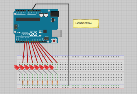
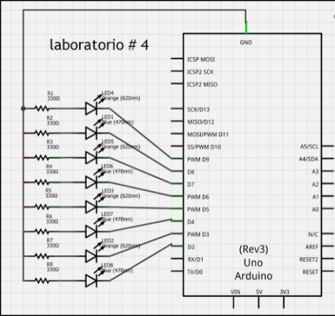
En el laboratorio 4 el objetivo es controlar 8 LEDs desde el Arduino, un LED encendido que se mueve en forma continua de izquierda a derecha, vía una interfaz gráfica en Processing/ControlP5 para controlar el tiempo de encendido y el tiempo de apagado.

LISTA DE ELEMENTOS UTILIZADOS:

a- El computador

b- Software “Processing”

c- Software “fritzing”

d- Hardware Arduino UNO

e- 8 Leds

f- 8 Resistencias

g- Protoboard

h- Alambre para protoboard

DIAGRAMA Y ESQUEMA

Captura

Captura

PROCESO MONTAJE

DSCF5161 DSCF5162 DSCF5163

CODIGO EN ARDUINO

#define MAXLED 8

int led[MAXLED] = {
2,3,4,5,6,7,8,9};
int marca = 0;
int prendido = 200;
int apagado = 100;
int i=0;

void setup()
{
Serial.begin(9600);
for(int i = 0; i < MAXLED ; i++)
{
pinMode(led[i], OUTPUT);
}
}

void loop()
{
if (Serial.available() > 0)
{
marca = Serial.read();
if(marca == ‘p’)
prendido = Serial.parseInt();
if(marca == ‘a’)
apagado = Serial.parseInt();
}
prender(led[i], prendido);
apagar(led[i], apagado);
i++;
if (i>MAXLED) i=0;
}

void prender(int l, int t){
digitalWrite(l, HIGH);
delay(t);
}

void apagar(int l, int t){
digitalWrite(l, LOW);
delay(t);
}

CODIGO PROCESSING

import processing.serial.*;
import controlP5.*;
ControlP5 cp5;
Slider slider1;
Button boton1;
Knob perilla1;
Serial puerto;

void setup() {
size (600,400);
puerto = new Serial (this , Serial.list()[1],9600);
cp5 =new ControlP5(this);
// cp5.addSlider ( “tiempo”, min, max, inic, posicionX, posicionY, tamañoX, tamañoY );
slider1=cp5.addSlider(«tiempo»,0,1000,200,40,40,300,40);
// .setColor( new CColor( fore, back, act, labe, value ) );
// #FFFFFF (#RRGGBB) // 0xFFFFFFFF (0xTTRRGGBB)
slider1.setColor(new CColor(#00FF00,#808080,#FF0000,#FFFFFF,#FFFFFF));
boton1 = cp5.addButton(«aceptar»,50,40,100,80,40);
perilla1 = cp5.addKnob(«energia»,0,500,150,400,40,100);
perilla1.setColor(new CColor(#00FF00,#808080,#FF0000,#FFFFFF,#FFFFFF));

}
void draw(){
background(130,450,360);

}
void controlEvent(ControlEvent theEvent){
String nombre=theEvent.getController().getName();
int valor=int(theEvent.getController().getValue());
println(nombre+valor);
puerto.write(nombre+valor);
}

FUNCIONAMIENTO

Laboratorio 2

Publicado: 10 09, 2013 en Laboratrio 1

DESCRIPCIÓN:

Este montaje es exactamente igual al de los 8 LEDs, pero añadiendo un potenciómetro. Este ejercicio consiste en controlar 8 LEDs encendidos que se muevan de izquierda a derecha según la posición del potencimetro.

MATERIALES:

8— resistencias de 220 ohmios
1 — plataforma arduino uno R3
1 — protoboard
8 — leds
1 —  potenciómetro

DIAGRAMA Y ESQUEMA

protoboardesquema

PROCESO DE MONTAJE 

DSCF5157 DSCF5156

CÓDIGO

CODIGO

FUNCIONAMIENTO DEL ARDUINO